| Optical Design | ZeMAX Optimisation | CAD Development | Lens Barrel Cutting | Lens Optics Turning | Testing | Video Results |
 |
 |
By picking realistic global parameters for the lens such as target aperture, focal length, back focal length and lens arrangement type, I used books and the internet to work through the mathematics required to work out the geometry of the lens. |
 |

|
Basic designs only get you so far, so once basic geometry has been figured out for a roughly symmetrical lens, it is entered into optical design software for further development. ZeMAX is an industry standard and can be used to add, alter, and optimise optical surfaces according to a merit table of priorities and the lenses general specification. |
 |
 |

 |
Once the geometries have been signed off, they can be exported and used in the more familiar product design work flow. The flat DXF is revolved and the lens barrel is built around it making considerations for aperture ring access, BFL clearances between the rear lens and the sensor, focus movement and camera bayonet fitting. |
 |

|
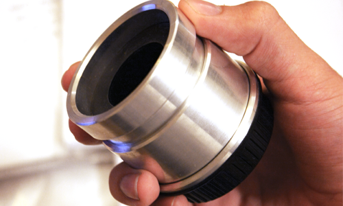
The cutting of the lens barrel is fairly simple using standard machinery such as metal lathes. I ensured that I cut multiple copies at once so that I would have enough parts to build multiple prototypes. For bayonet fitments, reverse ring adaptors for Canon EF and Nikon F mounts were trimmed and mounted to the bottom of the aluminium housings. Although the focus is a loose push pull system, the tolerances are still kept as tight as possible, to within +/- 0.5mm diam. |
 |
 |

 |
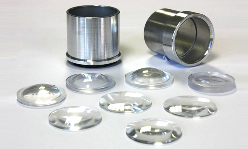
Cutting the optical components was difficult. This is where the majority of my research has been. Multiple attempts to create the perfect surface resulted in me learning how to manually G-Code a CNC lathe and cut billets using custom HSS tools created avoid collisions when cutting concave faces. Holding the lens in reverse also required diameter specific aluminium collets to be built, holding the lens on a 1mm edge diameter only. |
 |
|
Once complete, the lenses were taken back with me to France to be tested. The results varied, and lessons were learnt from each prototype. The lens were also given to artist photographers to see how they could utilise the image errors in artistic ways. Over all, the resultant images are interesting and informative, and have helped me assess what I have learnt. I will now continue along a new strategy by outsourcing manufacturing and concentrating solely on design, with more complex focus mechanisms in the works using 3D printed parts. |
 |
 |


